The machine is inspired by 4-chip Z80 computer, with ChibiTerm single chip VT100 terminal added in. I chose to redesign the system from ground up, to minimize licensing issues, although ChibiTerm still has Creative Commons license. I do intend to follow up with the second version that would have a different video interface. Z-One served its purpose as a development platform for creating MCU firmware, Z80 monitor, and getting SD card interfacing working and CP/M ported.
The design is mainly driven by simplicity of building the system. The initial version ran good and stable assembled on solderless breadboard, so you can pretty much wire it up any way you want, with a caveat that ChibiTerm part needs some care and attention to keep ground and power noise free for best image quality on VGA. You do need to be able to program AVR microcontrollers and also ST microcontroller, but programming tools for these are very cheap and easily obtainable from eBay. Once the microcontrollers are programmed, the system itself can be used to initialize SD card, and download application software over the auxiliary serial port that has USB to serial converter on it.
The features of the machine, as of Jul 2018, are:
- Z80 running at up to 4.6Mhz, changeable in MCU firmware
- Memory address space filled with 64K RAM
- CP/M running, with maxed out storage on SD card (16x8MB drives). You need at least 256MB card.
- ATMega1284P as system controller:
- Provides system clock for Z80
- Contains and serves bootloader, monitor, and CP/M binaries
- At startup, patches Z80 bootloader into first 128 bytes of RAM
- SD card interface and initialization
- Console port for Z80-ChibiTerm connection, using UART at 115200
- Heathkit H19 terminal emulation, with special keymappings for WordStar
- Software implemented auxiliary serial port connected to FTDI based USB-Serial converter, up to 19200
- Interval timer with 10ms resolution
- Integrated ChibiTerm
- 80x30 character text with analog VGA connector
- Inverse text and line drawing characters
- PS/2 keyboard, US layout only
- Boots into system monitor if no SD card, that has
- Commands to examine and change memory
- Built in Z80 disassembler
- SD card read/write sector commands
- Can read/write I/O ports
- Can run code, examine registers
- Download Intel Hex file from auxiliary port
- Wait logic for adding 2nd MCU
- Runs from 5V, with modern CMOS Z80 and HCT series logic chips uses less than 70mA
There are some known bugs and issues:
- Chibiterm firmware has a bug that makes arrow keys work wrong when caps lock is on.
- Because of interrupt latency, the I/O through the ATMega is pretty slow. This mostly affects SD card access where most of the time is spent transferring data between ATMega and Z80, with Z80 sitting in wait state, waiting for the ATMega to service the interrupt. The disk is still a lot faster than typical drives of the CP/M era, though.
- Z80 cannot be clocked at higher speed, because ATMega is then not able to release bus fast enough for Z80 I/O reads. Again, 4.6MHz is still pretty good compared to the old machines.
- Although modern VGA monitors can all display 640x480 pixel resolution, all have much bigger native resolution and most are the size of aircraft carrier deck. If you want to go smaller, the price goes through the roof.
Software
All software and Eaglecad files are avilable at my github repository, MIT licensed.
Hardware
Click on image below for full size schematics.
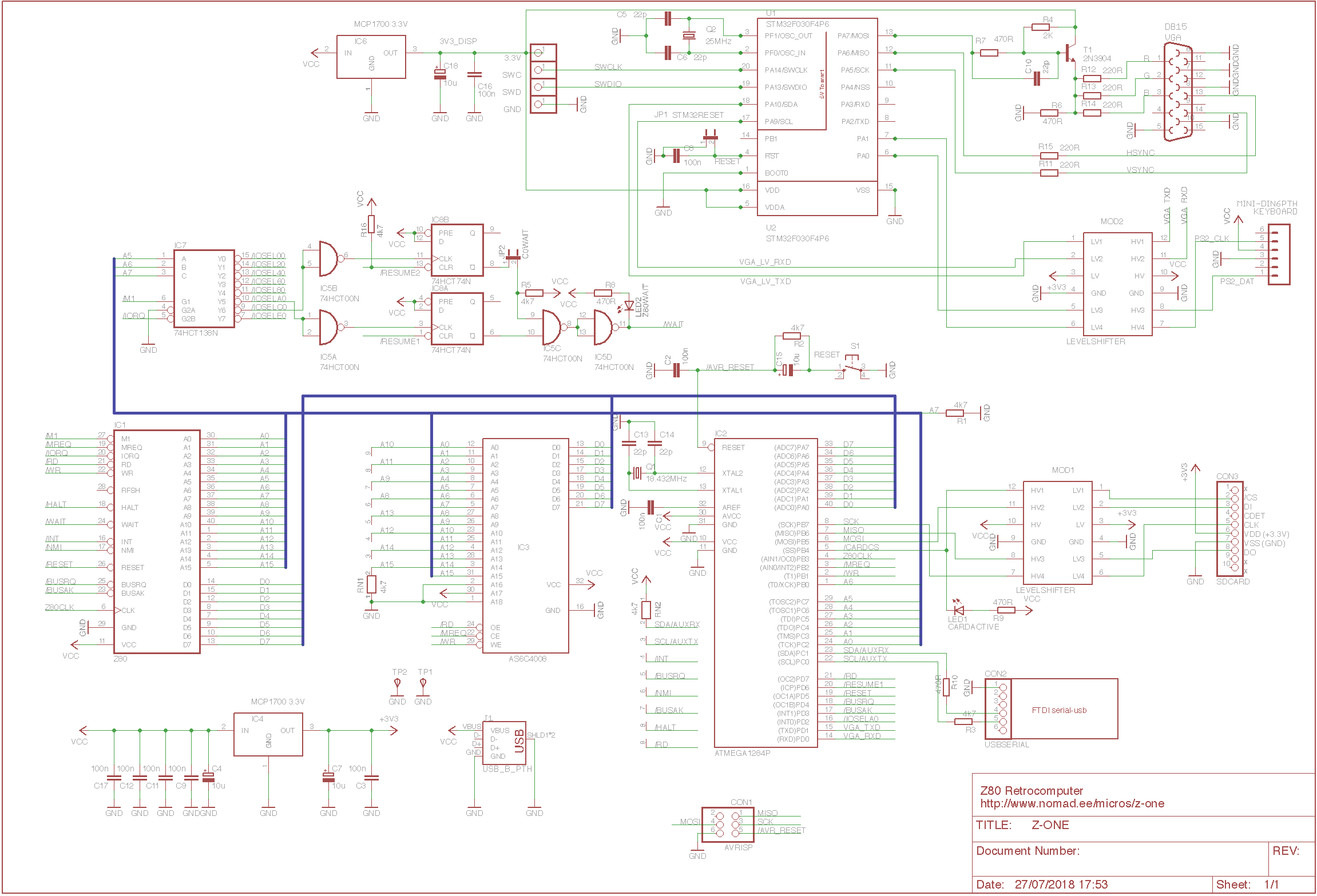
Video and keyboard are handled by Chibiterm part, built around STM32F030F4P6 microcontroller. This is a complete VT100 terminal emulator, and is connected to ATMega over logic level conveter module. The connection is at 115200 bps, no handshaking as the ST microcontroller is fast enough to handle everything at full speed. The video part is getting its power supply from separate voltage regulator, to isolate it from a rest of a circuit. For programming the microcontroller, you need ST-LINK v2 compatible programmer. These cost $2-$3 on eBay, and you have quite a choice of colours. Just search for "ST-Link V2 Programming Unit mini". Get the stlink tools from https://github.com/texane/stlink.
To program the ChibiTerm part, clone my fork of ChibiTerm from github, this includes the prebuilt firmware image.
git clone https://github.com/mastmees/STM32F030F4-VGA.git st-flash --format ihex write STM32F030F4-VGA/STM32F030F4/Firmware/ChibiTerm/Objects/VGA.hex
At least on OSX, the programming sometimes fails, usually you can overcome the problem by just shorting the reset jumper for a moment to reset the STM32F030F4P6, and trying again.
ATMega1284P does most of the heavy lifting. It is connected to SD card over another logic level converter and FTDI FT232RL based USB to serial converter module. Most of its I/O is tied up for being able to be a bus master for the machine, so that it can take Z80 off the bus, write boot loader into memory, and then start the Z80. For programming the ATMega, you need an AVR programmer. Serching for "USBtinyISP AVR ISP" on eBay turns up what you need, you can get one for few dollars. Note that most of these do not use the correct buffer chip for programming 3V systems, but in this project the AVR has 5V supply, so no problem. If this bothers you, get a kit from adafruit.com that has the correct type of buffer chip, or be prepared to replace the buffer chip on the chinese version like I did.
For the memory, AS6C4008 from Alliance Memory is used. It is a 512K device, so most of it is not used. It's smaller brother, the AS6C1008 should also work, although I have not actually tried it.
IC8 decodes I/O space into 8 32-address slots. Two of this are then used for logic that puts Z80 into WAIT state whenever that I/O slot is accessed. I/O space A0-BF is used for interfacing with ATMega, C0-DF has the same functionality in case another microcontroller needs to be added to the system in similar way. To avoid accidental locups, there is a jumper JP2 that needs to be shorted to enable the WAIT state for Z80. ATMega can then release the Z80 by toggling the /RESUME1 signal low.
The system reset is handled by ATMega, it will halt the Z80, patch bootloader into RAM again, and then reset the Z80. Note that ChibiTerm part is not reset.
Most of the components can be bought off eBay for cheap, such as connectors, USB-Serial converter module, SD card connector module, and bidirectional logic level converter modules. I built the first version with Z80 and logic chips scavanged from old junk, but modern CMOS chips will result in much lower power consumption. You probably have to buy the RAM chip and microcontrollers anyway, so the 3 logic chips needed do not add much to the materials bill.
If you decide to build on a PCB then the entire package of CAM files for ordering a PCB from Elecrow.com is available in the software repository (see below). They do have a minimum quanity of 5 boards. With just a little patience you can also assemble the machine with point-to-point wiring on breadboard, using a SSOP to DIP converter board for ST micro, these are available from eBay. On the PCB you can either solder the ST micro directly to PCB, or use the ST microcontroller on the DIP converter board.
Start the assembly from 3.3V voltage regulators, check that the supply voltages going to ST micro and SD card are both 3.3V. You can assemble and program the ChibiTerm part first, when successfully programmed the monitor should show a blinking cursor on upper left corner, and kayboard caps lock light should turn on and off as expected. When assembling on PCB, I started from physically lowest components such as resistors, crystals, and capacitors, then chip sockets and such, just to make the assembly of the small components less fiddly.
Once assembled, and ChibiTerm part working, it is time to program the ATMega. Do not insert the SD card just yet. Assuming you have gcc-avr, pyx80, make, and avrdude correctly installed, issuing
make flash
should build everything, and program the firmware into ATMega. In case you do not have all the tools installed, a prebuilt binary is included in the git repository. On OSX, you can flash the prebuilt binary withavrdude -F -P usb -B 5 -c usbtiny -p m1284 -U lfuse:w:0xE7:m -U hfuse:w:0xd9:m -U efuse:w:0xff:m -U lock:w:0x3F:m -U flash:w:z80_tiny.hex -U eeprom:w:z80_tiny.eep
If the programming works, and it is your lucky day, then the machine should come to life, you should be seeing a system monitor prompt on the screen, and be able to type commands on the keyboard. Try U 0 to see the disassembled listing of the Z80 bootloader for example.Getting the CP/M software to the machine
Now you can insert an SD card that has nothing of importance on it, and press reset button. ATMega firmware should detect that the SD card is present, and offer you to partition and initialize it for CP/M. Once completed, the system will boot into CP/M and you should be looking at the nostalgic A> prompt.
All the 16 drives are 8MB in size, and nothing on them at this point. Remove SD card, press reset to get into monitor, and enter H command to receive hex file. Then, from the machine connected to the auxiliary serial port over USB, send the ymodem.hex file to the Z-One. For the OSX, and probably linux, you can use the provided isend.py script, just update it with correct device name. All it does is setting up the serial port correctly to 9600 bps, then sending a text file with 0.1 second delay at line ends. Once you have send the hex file, and Z-One monitor is happy about it, insert the SD card again and press reset. The CP/M application area from 100H up to monitor start at the end of RAM will not be touched by boot process, so back in CP/M you can just enter SAVE 8 YMODEM.COM to store the program on any drive you want.
The YMODEM is a small batch-receive-only implementation of YMODEM protocol. On the host computer side, you can use your favorite terminal emulator, but there is also xysend.py script that can be used on OSX to send many files in one go from command line. Update the device name if needed, then collect your files to a directory on host machine. On Z-One, go to a drive where you want to store the received files, and run ymodem.com. Then, on host machine, do python xysend.py yourdirectory/*. On Z-One just press any key to get out of the ymodem, and you are all set.
ATMega firmware
On startup, ATMega I/O is initialized, and interrupts set up. Then the consoler is cleared, and the firmware tries to initialize the SD card. If a card without expected partitioning is found, the user is offered to format it. After that, the bootloader is stored into Z80 RAM, and Z80 is started. From that point on, ATMega is sitting in main loop, waiting for interrupts to happen.
In general, Z80 I/O requests are handled in main loop to keep the interrupt handling time minimal, as long latency in interrupt handler would mess up the interval timer and more importantly auxiliary serial port that is implemented in software. The only exception is copying data that was read from SD card to Z80, this is done directly in interrupt handler to impove the read speed (when bulk reading data, Z80 spends most of its time waiting for the ATMega to service the interrupt).
console.cpp contains code that interfaces with ChibiTerm over UART, and implements Heathkit H19 terminal emulation on top of VT100 that ChibiTerm provides. A much cleaner approach would be to just change the ChibiTerm firmware over to H19 emulation, but as this is restrictively licensed and I want eventually to use something different anyway, I decided not to mess with it.
Software UART is interrupt driven, and uses two timers to transmit and receive data. When sending and receiving at a same time two interrupts happen for every bit duration, so you can only push it so far until other interrupts start messing up the bit timing. It does work reliably at 19200, this is what I'm using for the ymodem. Considering the small size of files in CP/M world, 19200 bps is not too bad at all.
SD card access code was, I think, the most challening piece of code. Lots of experimentation went into it, but now it works with every SD card that I own. In case another oddball pops up that gives problems, I left all the debugging code into source. Just change the #define noDEBUG to #define DEBUG at the top of the sdcard.hpp, and you will get lots of debug output on console.
The SD card formatting code is in partitioner.cpp. All that it does is creating a partition table, and filling directory areas on all CP/M drives contained in the first partition with 0xe5. The card space that is left over from 16x8MB drives is allocated to 2nd partition that and only be addressed with raw SD card sector reads and writes. Think of it as a 'tape drive'.
Z80 firmware
All Z80 firmware, including the CP/M, is provided in source code form suitable for compiling with pyz80 cross assembler that is written in python, so should run on any platform.
There are 3 pieces of code - the bootloader, monitor, and CP/M image. All 3 are built into ATMega firmware. Bootloader is patched into Z80 RAM at system start. Monitor and CP/M image can be transferred to Z80 on request.Once the bootloader is in RAM, and Z80 is started the bootloader code first checks if there is SD card with expected partition type inserted. If valid SD card is not found, then the bootloader transfers system monitor image to RAM, and jumps to monitor. If there is a valid card, then the bootloader transfers entire CP/M system image to RAM, and jumps to cold boot vector of CP/M BIOS.
The system monitor was written from scratch, and includes Z80 disassembler that is able to decode all officially documented Z80 instructions. It does not try to be too clever, as it will probably not get much use once the system is up and running. I used it quite a bit for debugging when bringing the machine up. Can probably be optimized a little and cleaned up a bit, especially in disassembler part.
I chose not to store CP/M system image on SD card, as it would make bootstrapping the system from blank card harder. As the CP/M source code is now available, it made more sense to build a complete image, with BIOS included, and make it available to the system. Obviously bootloader can be enchanced to look for bootable system on first drive, and load the system from card instead.
The CP/M image was produced based on Clark A. Calkins disassembled version. Few typos were fixed, and syntax change to make it palatable to pyz80. All the strings were also converted back to upper case to match the original Digital Research code, and other data was also made identical to original code. I compared the assembly result to a CP/M image of a working 63K system to ensure it was identical.
The CP/M BIOS is pretty lean, thanks to ATMega doing most of the work for SD card, console, and aux serial port. I wanted to make maximum amount of storage available, so 64K system was not possible because of the disk buffers. The only clever bit in the BIOS is that the boot welcome messages are printed by code that is stored in data area at startup. That part of the code also modifies the cold boot code to make sure that it is never invoked after the system has been started.