Modules
RF modules are produced by several companies, and sold by a large number of resellers and mail order outlets. You have a wide selection of working frequencies, and also several modulation methods to choose from. Some of these are:
| Frequency (MHz) | Use |
| 173.250 | European (10mW), UK (1mW) VHF frequency |
| 418.000 | UK UHF frequency |
| 433.920 | European UHF frequency |
| 869.850 | New European UHF frequency (EN 300 220-1, EN 300-683) |
| 914.500 | North American UHF frequency (FCC part 15) |
There are other frequencies (around 300..315 MHz, 916.5 MHz) but I do not know which countries they are for, as each country can pretty freely choose which exact frequencies are allocated to license free use and for what purpose.
Generally, manufactures have a module with the same pin layout for several frequencies, so that you can change to different frequency for different region easily. Data sheets are usually one-sheet leaflets which show you vital characteristics like power requirements and pin layout, so you cannot really tell much about operation from them. As rules of a thumb:
- FM modules are technically better (faster data rates, longer range), but more expensive. Most of the modules you can get without selling you car are some variation of AM.
- AM modules usually don't have carrier detect output and receive noise if there is no active transmitter
- Cheaper transmit modules are built around SAW filters and often do not comply fully with strict European regulations. It does not matter if you do not need you device officially approved.
- Antenna selection and placement is the most critical factor for available range.
Here are some useful links to producers and resellers
- Velleman - RX433, TX433
- Wen Shing - producer of Velleman modules and several others
- RadioMetrix - has its own modules, and useful documentation available. On an expensive side, though.
- Ming Microsystems - has its own modules, these are also sold at DigiKey.
You can expect to pay around $10 or a bit less for low price end transmitter and receiver modules, although you can go close to $100 for expensive ones. I bought mine from a local electronics store:
|
This transmitter module is produced by Chinese company Wen Shing. The company has wide product line of RF modules which are sold by various resellers under their own name. Velleman sells this transmitter as TX433 with a matching RX433 module, both by Wen Shing. |
 |
| Receiver module is sold by Jablotron as a building block for security installations under the REC-5 name. I bought this because it was available at our local electronics store, Velleman RX433 could have been ordered, but with 1 month delivery time. Ouch. | 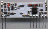 |
Antenna
Although antenna is by far the most critical component in terms of range and signal quality, there are actually just few options to consider. They are helical coil, loop of PCB track, and a simple whip antenna. Helical coil is very small, and easy to create by winding a piece to coil with about 4mm diameter. PCB track works well if you are developing a whole new product with proper PCB. Both detune badly with proximity of conductive objects. Whip antenna is just a quarter-wave length of straight wire or PCB track (about 15.5 cm for 433.92MHz), by far the easiest for hobbyist to use. Properly placed, whip is a best performer and suffers the least from proximity problems. A nice at-a-glance overview and antenna drawings are provided by Radiometrix for their modules, but they work the same for all of them. Radiometrix app notes also show you how to reduce the power output of a module if you need to do it for FCC regulations. I used 15.5 cm piece of 0.7mm enameled wire at both ends.
Transmitter
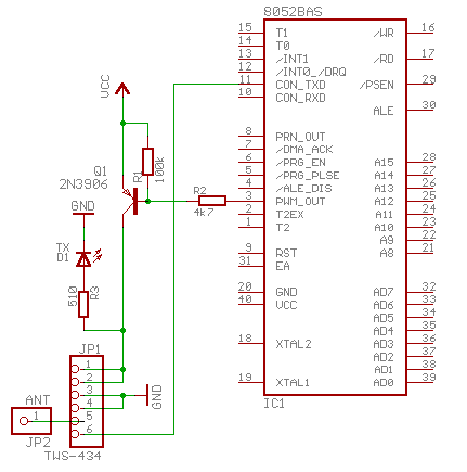
As you can see, transmitter is a really simple affair. All you need is a power switch, because the transmitter module emits carrier whenever it is powered on. Q1 opens when its base is driven low via R2, and supplies power to D1 led and RF transmitter module. Once powered, the transmitter broadcasts all data that is sent to console port. The module works reliably at 2400 bps, so you will have to set the console baud rate to this relatively low value. However, if you have the PRN_OUT pin free (I had it allocated to another experiment) then you have better option to use this as transmitter output, and use PRINT# to send data out. Printer output baud rate is programmable at run time using BAUD statement (in fact, you have to do it because otherwise the timer will not be initialized and you get something like 1 bps speed).
Receiver
The receiver is built to be connected to PC serial port. As it is powered from unused data pins, it may not work with new laptops that only supply about +-5V instead of desktop PC+-12V at RS-232 interface. 78L05 low power linear regulator is used to regulate this voltage down to +5V for receiver module and MAX-232.
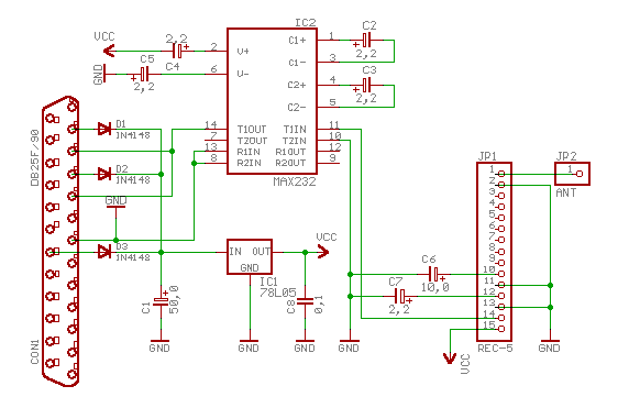
You cannot see the pin number on serial connector, but pins 2 (TXD), 4 (RTS), and 20 (DTR) are wired to diodes; pins 3 (RXD) and 5 (CTS, optional) are wired to receiver output via RS-232 level shifter chip; pin 7 (GND) is connected to GND.
| The whole thing can be easily assembled on a piece of veroboard that is stuck between connector pins, the receiver can then be plugged directly to 25-pin serial port, or to the end of a straight-through modem cable. My version looks like this. | 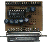 |
Operation
First of all, the receiver is continuously trying to listen to he carrier, and as it has no CD output, you cannot really tell if it outputs garbage or sensible data. The receiver output behaves like this:
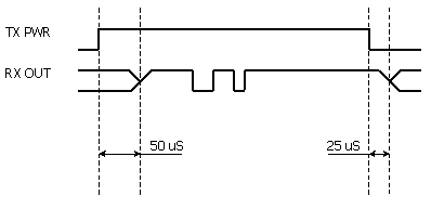
If the transmitter is not powered, or is not in range then the receiver outputs random noise. Once you power up the transmitter, it takes about 50uS for a transmitter to stabilize and receiver to lock on to carrier, at which point the receiver output goes high. As the bits are transmitted, the receiver output tracks the transmitter input fairly well. When the power is removed from transmitter, the receiver output stays high for about 25uS, then starts outputting garbage again.
Keeping this in mind, you should design you protocol to include a 'frame header' character, and for good measure send one sync byte before frame character because first byte transmitted tends to get garbled from time to time.