X-10 is an ancient powerline communication protocol that refuses to die because it runs over existing mains cabling, and is deceptively easy to get started on. Once you actually start, though, you'll notice that all the modules are very expensive for what they contain, but the worst thing is that the communication is not even close to reliable in modern household.
Why filters?
There are two reasons why the communication is unreliable. In multi-phase installations the transmitted on one phase is not usually heard by receivers on other phases unless a phase coupling device is installed. But thats straightforward, and usually resolves a problem (you may have to resort to active repeaters in some cases though).
The biggest problem is 'living together' with other devices on the same cabling. Some devices emit noise to cabling that can swamp the low-level X-10 signals entirely. Many modern devices have heavy filtering on the mains side of the power supply to avoid emissions, but by having these the devices turn into 'signal suckers', in other words they also filter out the X-10 signals from mains.
The fix in both cases is the same - filters. A filter between a device and mains that blocks 120kHz passing though either way effectively decouples these misbehaving devices from mains, allowing X10 signaling to work.
My story here started when I bought two receivers and tried to control them from self-made transmitter. One of them worked, while the other on a same phase did not. I finally tracked the problem down to Yamaha radio power brick that was plugged into power outlet on a same phase near the non-working receiver. Once I unplugged it, the receiver started working. So I needed a filter.
Commercial options
The commercial options, expensive as they are, assume that you know which connector is live and which is neutral. The modern filters are notch filters made from capacitors and inductors. I simulated them in LTSpice to see how they would perform. Below are schematics of 3 commercial filters with frequency response plots.
Levitron 6287
Levitron 6287 is a notch filter, but the component values place the notch a little higher than 120kHz.
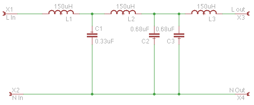
Levitron 6288
Levitron 6288 is LC low-pass filter, and uses big chunky inductors and capacitors
Filterlinc 1626
Filterlinc is the same notch filter as Levitron 6287 but the component values place the notch exactly at 120kHz.
DIY
So what I needed was something to put on the power cable, where I cannot be sure which side ends up being neutral.
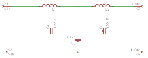
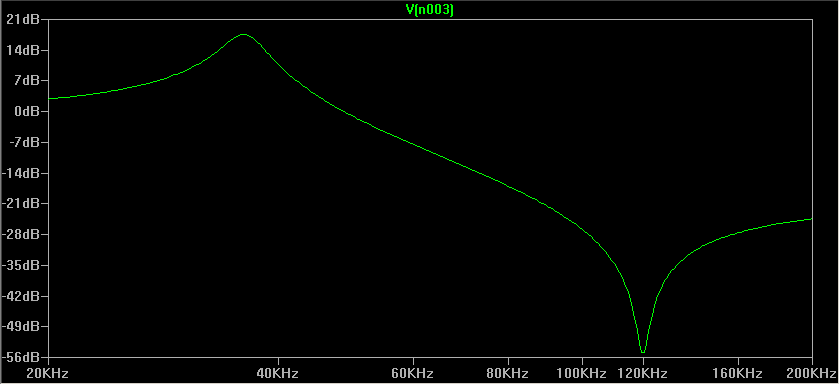
2 sided notch
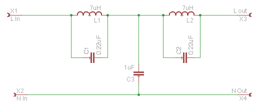
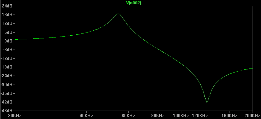
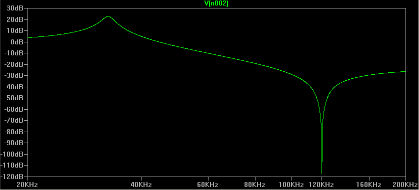
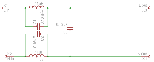
First thing I simulated was a symmetrical notch filter (note the changed component values, I checked what was available from local component store). 0.16uF capacitors can be made by wiring 150nF+10nF in parallel. straightforward, and gives good response as expected. Lots of components, though. (note that ideal inductors and capacitors were assumed here)
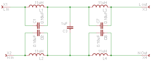
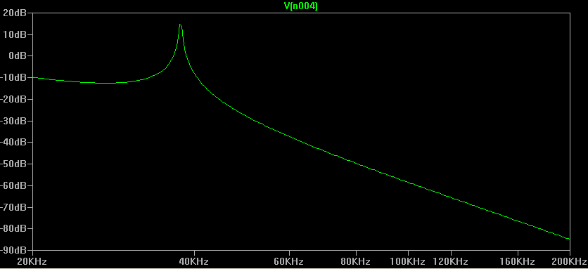
2 sided one stage
I then tested what would happen if I just drop the second half of the filter. Still works pretty well, even with small shunting capacitor. That was my initial plan before digging into my junkbox.
2 inductors
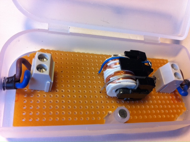
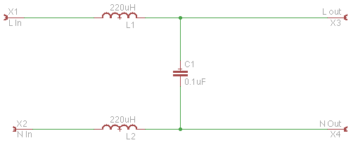
From the junkbox I found an old power supply board which looks like it originates from a copy machine, or laser printer. And near the mains socket, part of the emission filtering there was a dual coil the looked promising. Ignoring the magnetic coupling, this is what it looks like:
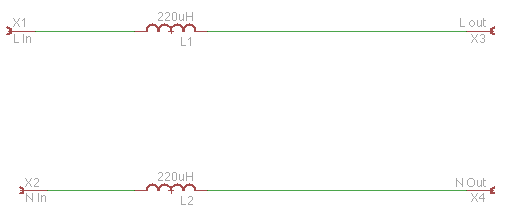
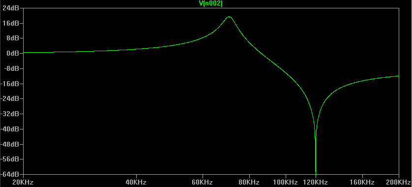
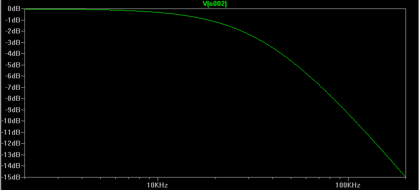
I quickly simulated what the coils (assumed 220uH inductance) would do - not too exciting on their own:
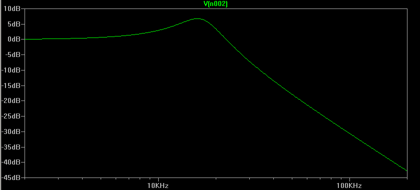
However, knowing that the power brick that goes behind the coils is a signal sucker (checked with scope, there was very little noise on mains phase) we can safely assume that there is some capacitance at the input there. Lets assume 100nF:
Now things looked much more promising.
So thats what I went for, without even bothering to measure what the actual inductance of the coils was. I took a small plastic box, made holes at either end, cut the power supply cable, and made a small board with two screw terminal and the dual inductor (mounted sideways, as it would not fit upright). I taped the box lid shut, and the thing worked right away - the receiver is happily clicking away with radio plugged in in the next room. This is how the inside of the box looks: