I wanted to use COB filaments as light sources in a project, but not use direct mains voltage to power them for safety. The filaments typically have forward voltage in order of 70V, and there are not many suitable power supplies available in that voltage range. I also did not know ahead of time what the exact voltage needs to be, so I wanted at least some adjustment possibility for output voltage. Most of the boost converter chips are for boosting battery voltage to regulated higher voltage, and very few are rated to that kind of output voltage without a use of external compontents. As in my application efficiency at light loads was not an issue, and output current would be constant I decided to roll my own version, controlled by 555 timer.
Hardware
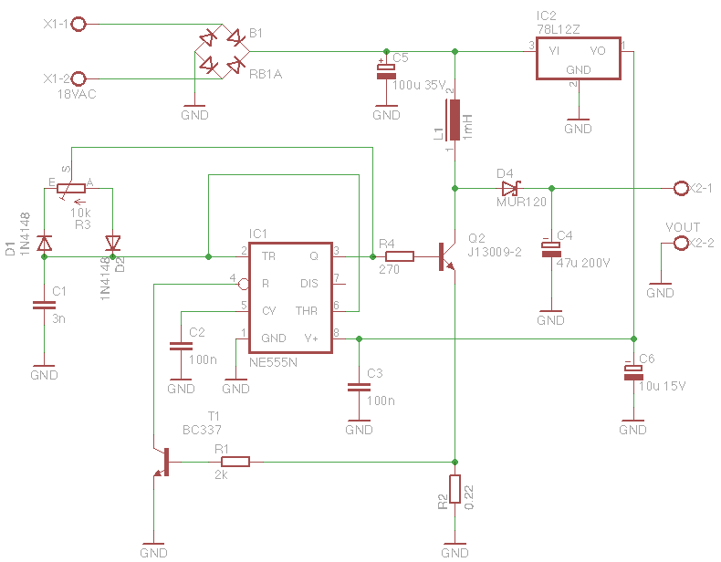
555 timer is used to generate PWM control signal for switching transistor, the actual PWM control part is formed by C1,D1,D2,R3 where the R3 and C1 values determine the switching frequency. The output of the timer is driving the switch transistor through R4. R2 is current sensing resistor, if a voltage drop on it exceeds about 0.7V silicon transistor voltage drop then the T1 conducts and pulls the timer output low. With the 0.22 Ohm resistor shown the current through switching transistor Q2 will be limited to about 3.2A. If your input voltage source is not able to supply destructive levels of current then you may want to omit R1,R2,T1 and connect the pin 4 of timer to pin 8.
IC2 is a linear voltage regulator for limiting the supply voltage for 555 timer, if the voltage on C5 does not exceed 15V that is typically specified maximum supply voltage for the timer chip then you can omit IC2 and supply the timer directly from input voltage.
The critical parts of the circuit are inductor, the switching transistor, and switching frequency. You want a good beefy inductor if your load current is more than few milliamps. Theoretically you would be able to use much less inductance at higher frequencies but higher frequencies make the switching element driving even more critical than it already is. I experimented quite a bit, and found that 1mH inductor and switching frequency around 30kHz works very well in the circuit shown. You do not want to make the switching frequency too high, then the next cycle would start before the voltage rise on the inductor has ended, causing excessive losses without further rise in output voltage.
The ability to boost the output is also heavily dependent on switching speed of the power transistor. While it looks tempting to use a power MOSFET for switching element, high voltage high power ones usually have gate capacitance that requires more drive current for efficient operation than 555 timer is capable of. The J13009-2 switch transistor is readily available from eBay, and dirt cheap. You can also often scavange these from old PC power supplies. J13009 has pathetic amplification ratio (typically the beta number is around 25), thats why you also need to drive it with significant base current, but it is still easier load than the MOSFET gate.
Depending on your situation you may want common-mode chokes on input and/or output to suppress the interference. You may also need a small heatsink for the power switch Q2, and with high input voltage you may need to use higher power 7812 or perhaps 7815 voltage regulator because at higher input voltage the power loss on the linear regulator will grow.
If you need higher output current then you will need to use higher current inductor and higher current D4. The electrolytic capacitors C4,C5 need to be low ESR types, with appropriate voltage rating for the input and output voltage. If you are using the circuit for COB filaments, 100V rating would be sufficient.
The output voltage of the booster is dependent on its input voltage, PWM fill ratio of the switching signal, and output load current. While this circuit can easily boost 12V to 70V, it is much easier to boost 24V to 70V with lower PWM fill ratio. Unless the voltage rating on C6 is very high you do not want to run the booster without any load on output. When testing, use a lowish input voltage and mark the position of lowest PWM fill factor on the R3 trimpot, and leave it adjusted there. Then connect the booster to its intended load, supply it with the input voltage that you intent to use, and adjust the R3 for required output voltage.