Simple serial terminal for development and debugging
Most of my microcontroller project start out from getting some sort of observable output going, even if it is just an I/O pin. Many small projects will actually not need any visually observable output device, but it would certainly be useful to have something during development.
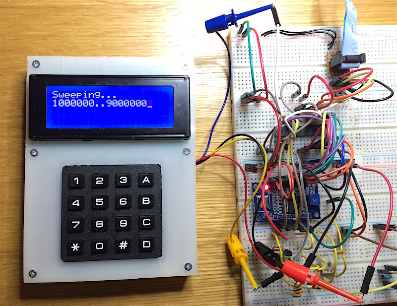
There are many options to go for, I chose to build a simple logic level 'terminal' from 4x20 line LCD screen and 16 key keypad. For using it, there are 4 wires - +5V, GND, TXD, RXD. The transmit and receive are obviously logic level so that it can be directly hooked to logic level I/O pins.
Hardware
(Click on schematics for full size view)
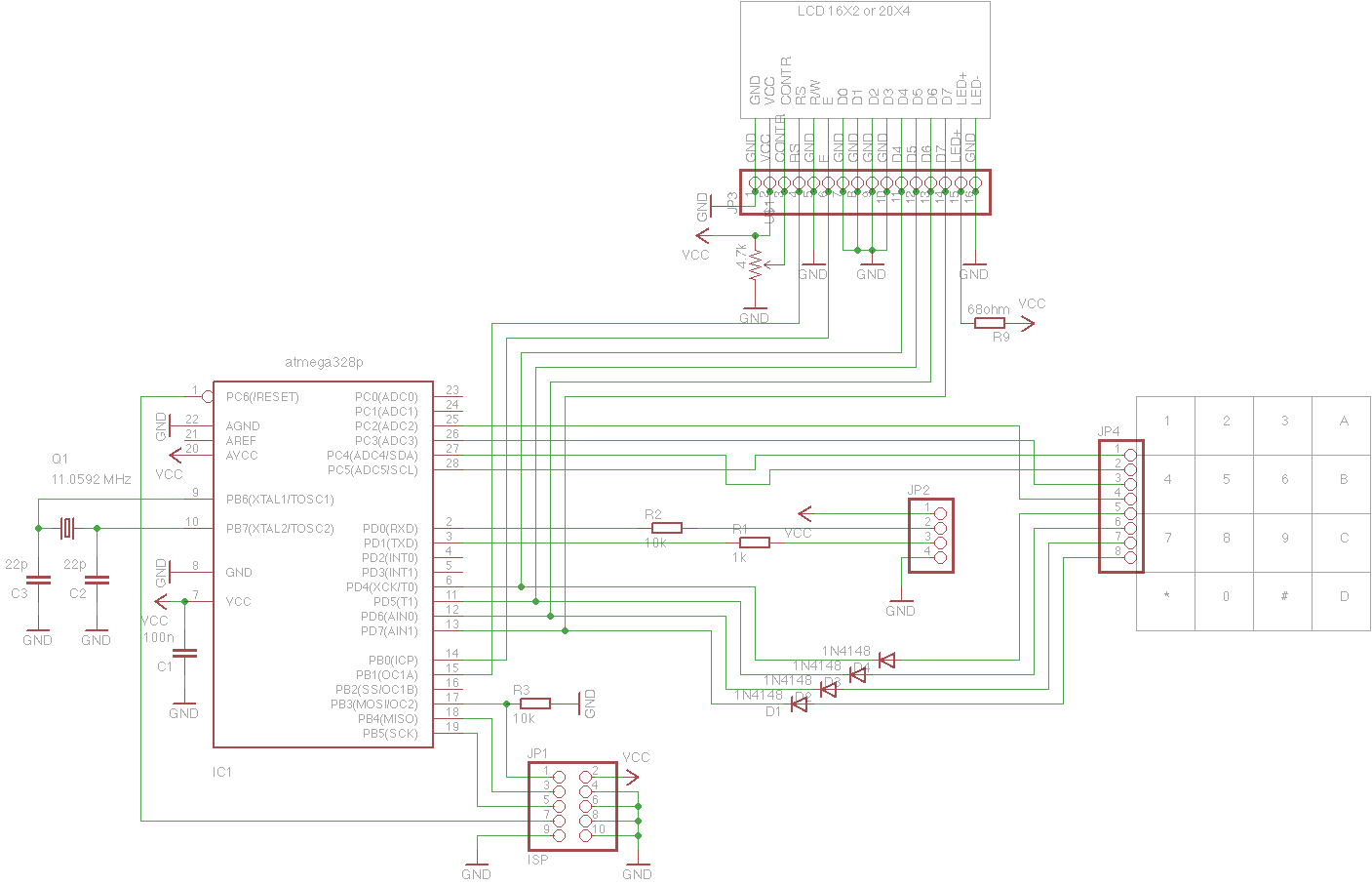
The hardware is super simple. I used Atmega328p but any mega8 series chip will work. JP1 is ISP programming and also serves as jumper block for selecting baud rate to use (more on that below). JP2 is an interface to the 'host', JP4 is for attaching 16 key keypad and JP3 is for standard text mode display. On schematics these are shown as connectors but you can obviously just wire a piece of protoboard to periherials with hookup wire, this is what I did.
PD4..7 form a 4 bit 'data bus' for both LCD, and keypad scanning. Each pin is wired to a keypad column through diode and PC2..5 are used to read back a row of keys. Port C pins have internal pullups enabled, and low level on column line results in low logical level on any port C pin where a key is pressed down.
You have to use external clock source for this project, the internal oscillator is not stable enough for serial data. The best frequencies are those that are evenly divisible with 115200, but for lower baud rates (like up to 38400) almost any frequency from couple of MHz upwards will work fine. I used 11.0592 MHz crystal that I had in my parts box.
Baud rate selection is with 3 jumpers on JP1, in the table below the rightmost jumper is on pins 1-2, middle jumper is on pins 3-4, and leftmost jumper is on pins 5-6:
| Baud | Jumpers |
|---|---|
| 1200 | ::: |
| 2400 | ::| |
| 4800 | :|: |
| 9600 | :|| |
| 19200 | |:: |
| 38400 | |:| |
| 57600 | ||: |
| 115200 | ||| |
For LCD screen I used this one, for keypad I used this thing, the pins are easy enough to figure out using ohmmeter. R1 and R2 are there for isolating the I/O pins from incorrect hookup, so you can simply try out which wire should go to transmit and which one to receive.
I wired up a big mess, and then fitted it into 3D printed box. The result in use looks like this:
Software
All C++ code is available at GitHub, in my debugterminal repository. I also made hex files available if you do not want to build the code yourself, but keep in mind that you will have to rebuild if you use a different frequency clock. For building you need a working make, avr-g++, and avrdude.
Building
Just type make, and you should get hex and eep files. make flash will try to write the code to microcontroller using avrdude with usbtiny compatible programmer. make clean will clean the clutter from directory, and make erase will try to erase microcontroller's flash memory.
Code contents
The firmware for the terminal is in debugterminal.cpp, lcd.hpp, uart.hpp, and keypad.hpp. You will need to update makefile if you want to use different clock frequency or avr device. For 2x16 LCD screen update the ROWS and COLUMNS in lcd.hpp
For reading keypad its scan function needs to be periodically called, and any keypresses are stored in internal buffer that can then be read later. The main loop does both, the period is determined by timer interrupt, although incoming serial data interrupt also results in keypad scan. I did not want to scan keypad in timer interrupt handler because the data bus is shared with LCD.
LCD output handler reacts to few control codes, everything else is just written to LCD as is. The control codes it currently recognizes are:
| '\b' | Moves cursor left, if at beginning of row then cursor does not move |
| '\v' | Moves cursor home - top left corner of screen |
| '\t' | Moves cursor right, the cursor can move one position past line end |
| '\f' | Clears screen and homes cursor |
| '\n' | Moves cursor down. If on last line already then scrolls screen up instead |
| '\r' | Moves cursor to beginning of current row |
Serial port handler is very simplistic. The received data is processed in received() method that is called from interrupt handler. Each received byte is simply stored into internal buffer which can later be checked with ready() and data can be retrieved with read(). If the buffer overflows then the excess incoming data is simply discarded. Data transmit is implemented with polling USART status bit, and send() method simply waits until a previous byte has been moved to shift register. There was plenty of code space, so for clarity I chose to calculate the serial clock divisor in code instead of allowing pre-processor to calculate these into baud rate table.
The main function just initializes everything and then sits in sleep-wakeup-process loop. Note that the baud rate setting jumpers are read on initialization, so you need to power-cycle if you want to change the baud rate. The baud rate table is in strange order because the first jumper is connecting to VCC instead of GND, that is just because of how my nonstandard ISP connector is wired.
terminal.hpp is an example on how to actually use the terminal in your project. Just set the baud rate appropriately, and then do something like this:
#include "terminal.hpp"

Terminal terminal;

...
terminal.init();
...
if (terminal.ready()) {
  char c=terminal.getch();
  process_input(c);
}
...
uint32_t f=1000;
terminal.clear();
terminal.puts("Value=");
terminal.putn(f);
terminal.putc('\n');
...
Enjoy.
Copyright © Madis Kaal 2000-