This is a follow-up on the using DL2416 example. With addition of cheap FM tuner breakout module, rotary encoder, and optionally an analog VU meter for extra fancyness you can build guts of FM stereo radio that can also decode station names from RDS.
Lets get started (click on schematics to open full size version in new window).

The circuit has two major logical section - radio module part, and the control part. You can build them on a same board, or to separate boards. I want two separate boards for a receiver project, so that the radio is close to antenna connector while the control board is located at the front panel.
Radio module carrier board
This board has a voltage regulator for 3.3V supply for radio module, and 3 level shifters for signals coming from control board. The Si4703 breakout boards are all clones of SparkFun FM Tuner Evaluation Board - Si4703, and it has "VCC is 3.3V only!" notice on the schematics. My modules, labeled "CJMCU-470" use 5V capable TPA6111A2 chip for headphone amp and the Si4703 itself is also 5V tolerant, so these boards do not seem to have anything on them that would limit the VCC to 3.3V. Nevertheless, I added level shifters and voltage regulator in case anyone wants to use the original SparkFun boards, in case these really are 3.3V only.
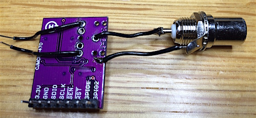
Modifying the Si4703 breakout board for external antenna
The breakout board is built to use headphone cable shielding as an antenna. This is obviously no good if you want to build the module into receiver that has a proper antenna, for example this one. Fortunately the mod is easy - you just need to connect the antenna to headphone jack's ground connector, and antenna cable shield to breakout board's ground plane. I removed the headphone jack and used the holes for antenna and audio output wires, but you can just solder on the new wires with headphone jack in place. Thats how my module looked for plugging into solderless breadboard:
Control board
The control board is build around Atmega168, with two DL2416 bubble display modules attached to it (just like here). I2C interface goes to radio board, along with one additional signal for configuring the Si4703 properly.
PC0 serves as ON/OFF input, pulling this input to ground 'turns on' the radio. The control board is obviously on all the time, but high level on PC0 input causes the display being blanked, VU meter and its backlight turned off, and radio also put into disabled state. In the off state the power consumption drops to about 10mA, while in the on state can reach 180mA or so, depending on what is shown on the display. Note that enabling the radio produces fairly heavy 'pop' on audio output.
PC1 is used to control VU meter backlight, it goes low when radio is 'on'.
Rotary encoder, such as Alps STEC11B01 is used for tuning, and pressing on the shaft-connected button saves the currently tuned frequency as default.
JP1 is ISP connector, in all my projects I've been using this nonstandard layout 10 pin connector that also allows taking 5V supply from USB port. It's great for building small projects on solderless breadboard. The encoder shares the pins with ISP connector, that is why I added R10,R11 there.
Optional VU meter
VU meter can be added to show radio signal level. The code reads RSSI value from the radio periodically and uses OC1A output to output PWM signal that is proportional to RSSI. If you do not want to use VU meter, then you do not need R13,D1,C4,TRIM1. These form a filter and rectifier to turn the PWM signal into analog voltage. If you plan to modify the code, then it is important to keep in mind that the OC1A output is also used as address A1 signal to displays. You have to stop the PWM generation before writing anything to display.
VU meter backlight modification
I wanted to use one of those small chinese VU meters. These swing full scale at about 0.5mA, so you do not need the control board that most sellers want to bundle for most cases. The backlight in these things is a small 12V bulb, and it is useless at 5V. Fortunately the meter is easy to modify. Just pry off the front, carefully because the scale may get stuck to front and needle is in front of the scale. You'll see the bulb in a back of a unit, replace it with led of whatever color you like, but before installing the led rough up its surface with sandpaper to diffuse the light better. I used orange led with flat top when prototyping. Yellow is probably a better choice, but I did not have any at hand.
Software
All C++ code is available at GitHub, in my silicon_radio repository. I also made hex files available if you do not want to build the code yourself. For building you need a working make, avr-g++, and avrdude. I have only build on OSX, feel free to contribute with build instructions for other platforms
Building
Just type make, and you should get hex and eep files. make flash will try to write the code to microcontroller using avrdude with usbtiny compatible programmer. make clean will clean the clutter from directory, and make erase will try to erase microcontroller's flash memory.
Code contents
Code should be quite understandable from comments. There are utility classes for display output, rotary encoder input, and PWM output for driving the VU meter.
Display is implemented so that it can show max 64 characters long text by scrolling it. This is the maximum length of text that radio text over RDS allows. Radio text is not shown as characters arrive, instead entire text block is collected, then stored in rds decoder to be used (and scrolled) when display changes to appropriate state.
The Si4703 control is implemented in 4 different files. Baseradio class defines interface that SI4703 class implements for specific chip. BaseRadio also has basic I2C reading and writing functions, and defines a generic RDS decoder. RDS decoder itself is implemented in separate file, the current implementation can decode basic info, station name, and radio text in its two different variations.
The main function after initialization runs in a loop where it goes to sleep, wakes up on any interrupt and sees what needs to be done in its current state. When radio is on, then the main loop calls radio.run() once every 4 timer ticks, and updates VU meter. radio_display() function is called on every interrupt to handle input and update display.
radio_display() has an array of functions that it calls in round-robin fashion. Each function may display something, and with it return value tells the caller what it did. The result may be that a next function is tried, the display is kept static for a while, or the display is scrolled to show longer text.
Enjoy.