What is inside small servos and how they work
Servo has 3 major parts - small electric motor with a controller board, gears to reduce speed and increase torque, and a controller with feedback mechanism that can senses servo position. The motor itself can freely turn in either direction, but in positioning servos the motion of servo axis is mechanically limited by feedback mechanism and usually some kind of dedicated mechanical arrangment.
Small servos have a common 3-wire interface. Black or brown for the ground, red for the power supply and orange for position control. Most servos that you can get in these days have digital control interface.
The digital control works by feeding a logic high pulse to servo with 20 millisecond interval. The length of each pulse is between 1 and 2 milliseconds, with 1 millisecond positioning servo to one end of its motion range, and 2 milliseconds positioning it to the other end of its motion range, 1.5 milliseconds being in the middle. The actual range of motion in degrees depends on model of a servo.
The feedback mechanism is usually a small potentiometer, about 5kOhm, attached to the servo axle. The controller board reads its value, and turns motor to appropriate direction to make the value correspond to required percentage of its motion range.
How to modify servo for continuous operation
To modify a positioning servo to continuous drive servo - basically a direction controllable motor with speed reduction gearing - you need to replace the feedback potentiometer with fixed resistors that always tell the servo that it is at about the middle of its motion range. Then giving it 1 millisecond pulses makes it turn one way, and 2 millisecond pulses make it turn the opposite way. The common advice is to replace the potentiometer with two 2.2kOhm resistors, but I've found this not to work as expected sometimes. A more reliable way is to put an arm at the end of servo, and manually position the servo to center position. Then remove the arm, open the servo, cut off the potentiometer and actually measure resistances on both sides of the center tap, then replace the potentiometer with appropriate fixed resistors.
Lets see some examples, dirt cheap china-made servos from eBay:
TowerPro SG-5010
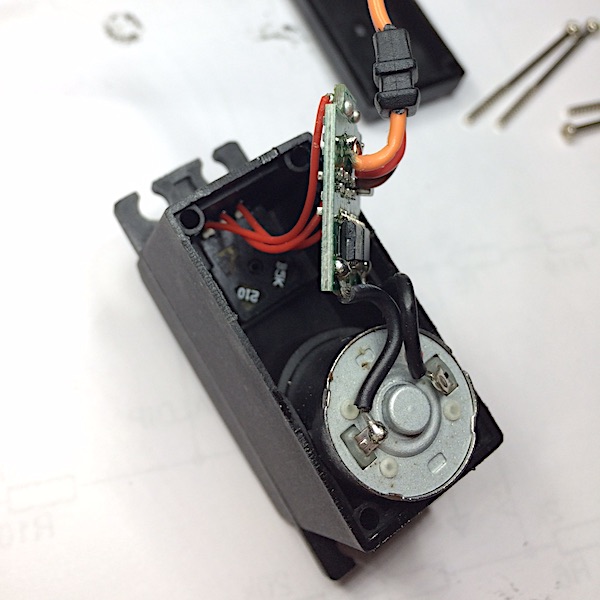
That one is all plastic pieces, and is not nice for modification. Once you unscrew the 4 screws holding the motor together, you can pull off the back plate and expose motor, control board and potentiometer.
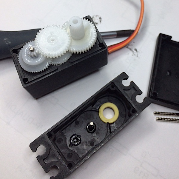
Carefully take the front off now, one gearing axle is actually in the cover, and the middle gear comes off with it. As you can see, there is a bump on the large gear - this is what mechanically stops the servo axle from turning further, and you will need to get rid of it by whatever method you have for cutting greasy plastic.
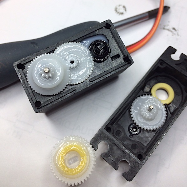
Now, when you pull the large gear off, you'll find that it is attached directly to potentiometer axle and is using the potentiometer as its mechanical support. You cannot just discard the potentiometer, you need to remove it, cut it open, and remove the inner parts that prevent the potentiometer from freely turning full circle in either direction. It is of course doable, but its messy and not quick.
Towardpro MG996R
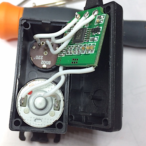
This motor has mostly metal gears and is much easier to modify because potentiometer is not used as integral part of gearing.
The back is similar to SG-5010, there is a motor, control board, and potentiometer.
On the front you can see that the large gear has a round pin in it as mechanical stop. This is just a press fit and can be easily pulled out with pliers.
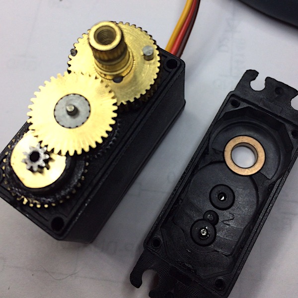
The the large gear has bronze bushings top and bottom, and in the bottom bushing there is a plastic piece that engages with potentiometer on one side, and with the gear on the other side. Take it off, and push the potentiometer into the housing, then remove it from back side. Thats the mechanical part done.
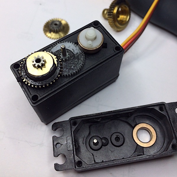
Replace the potentiometer with resistors, and you are good to go.
Copyright © Madis Kaal 2000-