Simple RS-232 to RS-485 converter with automatic driver control
I have been using a DIY RS-485 converter for years where automatic transmit control is built around 555 timer, but it has a problem that it enables the output driver when the RS-232 port has no signals on it. To eliminate this issue, I designed this circuit that is triggered from transmit signal falling front instead of level. The new circuit has less discrete components, is more precise and allows to adjust for different bit rates.
Hardware
RS-485 converter basically has two functions - to convert the voltages between RS-232 and RS-485 standards, and also to provide direction control for half-duplex RS-485. The direction control has many names, such as Auto-Turnaround, automatic send control, automatic flow control, automatic driver control and so on. It all means one thing - to enable the RS-485 transmission only when there is something to send, so that the bus is available for other devices to transmit on.
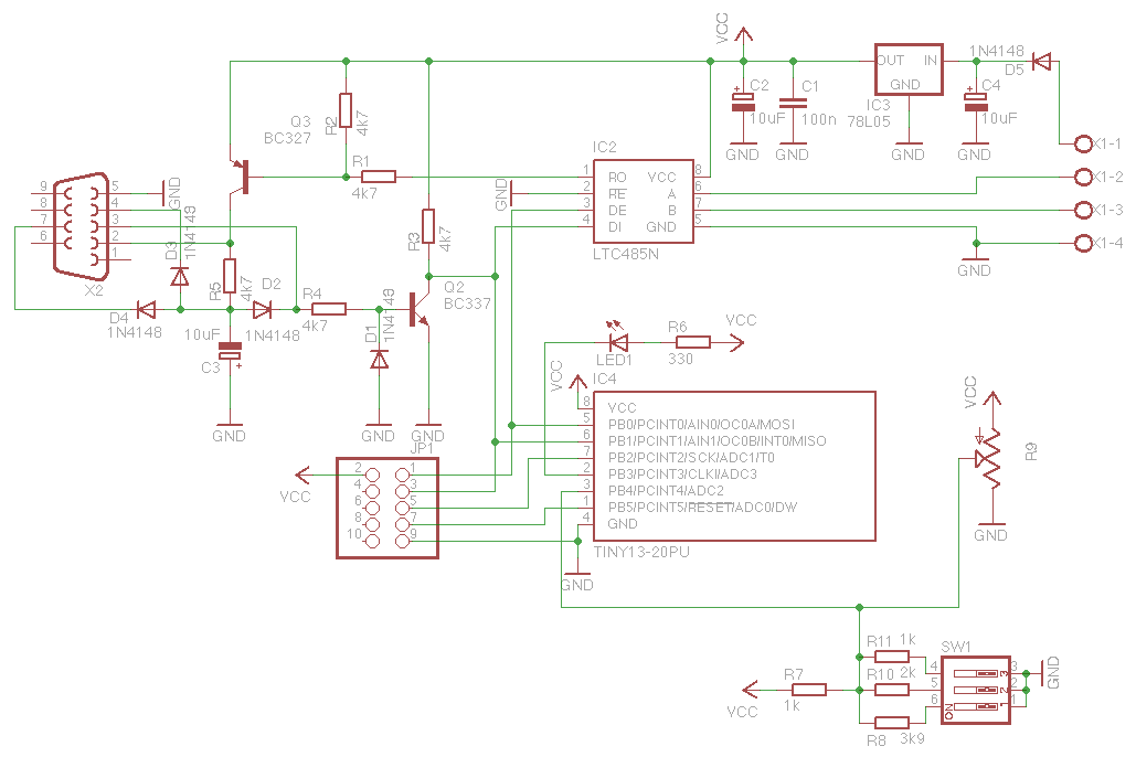
The negative supply rail is created from RS-232 signals (CTS,DTR and TxD) using D2,D3,D4 and C3. TxD also goes to level converter built on Q2, and logic level transmit signal goes to IC2 (RS485 interface chip) and IC4 (Attiny13 microcontroller).
Microcontroller generates driver enable signal on pin 5, and controls transmit indicator LED that is connected to pin 2.
The pulse is generated (or extended) on each falling edge of transmit signal, so that the driver stays enabled for 12 bit lengths from that edge. This means that the pulse is at least 10 bits long, but may become as long as 18 bits long from the beginning of start bit.
A trimpot is used to control the driver enable pulse length in 8 steps for common baud rates from 1200 to 115200, or alternatively DIP switches or jumpers can be used with 4 additional resistors (the TRIMPOT define needs to be changed in code) in this case.
The received data is converted to RS-323 levels using Q3. IC3 is for supplying 5V to the circuit, and D5 is for reverse polarity protection, obviously you need a supply voltage of around 8 volts at least. If you do not want to play with firmware then you can leave out the ISP connector JP1, and if you only need one fixed bit rate then you can leave out the trimpot and remove a bit of code.
Software
All C++ code is available at GitHub, in my rs485 repository. I also made hex files available if you do not want to build the code yourself. For building you need a working make, avr-g++, and avrdude. As usual, I have only build on OSX, feel free to contribute with build instructions for other platforms
Building
Just type make, and you should get hex and eep files. make flash will try to write the code to microcontroller using avrdude with usbtiny compatible programmer. make clean will clean the clutter from directory, and make erase will try to erase microcontroller's flash memory.
Code contents
The is not much of code, because it is basically just implementing front-triggerable timer using interrupt handlers.
On each falling edge of signal INT0 external interrupt handler is called. It enables RS-485 driver, turns on led, and sets up timer to fire after 12 bit transmit times. This is for worst case where zero byte is transmitted and driver needs to be enabled for start bit, 8 data bits and a stop bit based on the single falling edge of the data line. If the transmitted byte has other high to low transitions, then the interrupt will be triggered on each falling edge, extending the pulse so that it again last for 12 bit transmit times.
When the timer counter overflows, then the first invocation of timer overflow interrupt handler just disables the driver, but keeps the timer interrupt enabled, and LED on. This allows the timer to run another full period of about 28 milliseconds, and then the interrupt handler will be invoked again. Now it turns off the LED, and disables further timer overflow interrupts.
The main function just sets everything up, and then waits for interrupts to happen. Once an interrupt wakes it up from sleep, the main function resets the watchdog and if ADC has finished conversion calculates the timer load value from trimpot position for next time the INT0 happens.
Enjoy.
Copyright © Madis Kaal 2000-