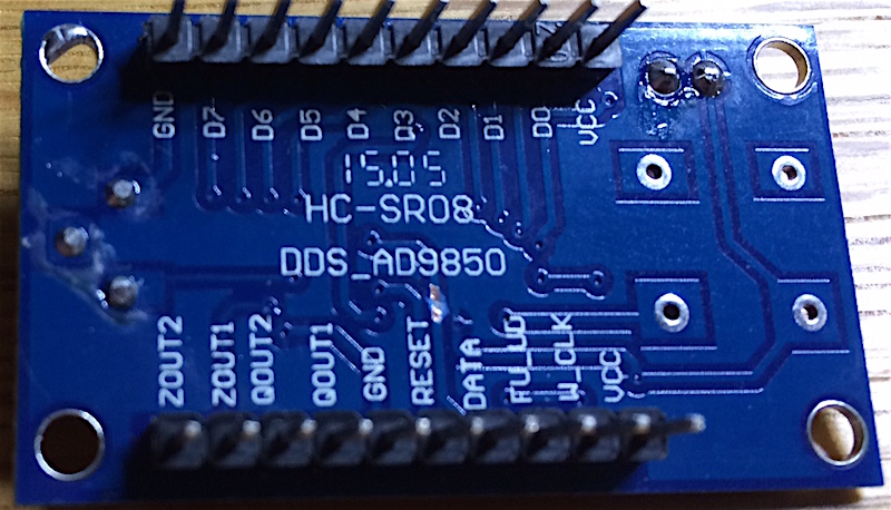
Step 1, modification of HC-SR08 module
Two modifications are needed to the board to enable amplitude modulation as described in Application Note AN-423.
First is to bring the RSET pin (12) out to connector. To free up the pin you have to cut the trace pin labeled as DATA, which is the same as D7 so you actually are not losing any signals. Once the pin is disconnected, its just a simple matter of soldering a wire from 3.9k resistor R6 to the freed up DATA pin.
This shows where to cut the track under the board:
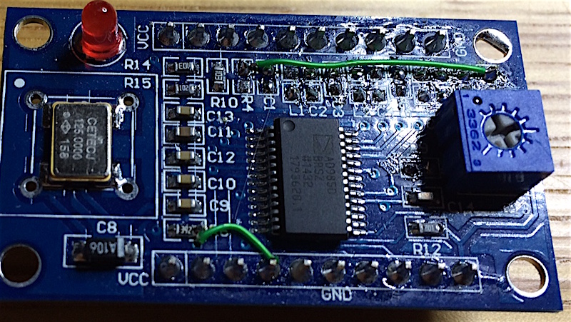
Second mod is to bring the current output pins directly, without load resistors connected to them, out of the board so that they can be hooked to to transformer as shown in application note. The output filter on IOUT output (pin 21) also needs to be eliminated. I simply removed all filter components and load resistors from the board, the list of removed parts is R4, R9, C1, L1, C2, C3, L2, C4, C5, L3, C6, C7, R5. Then to connect the IOUT to ZOUT2 pin of the module you simply solder a wire from a pad closer to board edge of R4 resistor to pad of R5 resistor, also closer to the board edge.
This is how the board looks after both modifications:
Step 2, the hardware
Clink on schematics to get full size view.
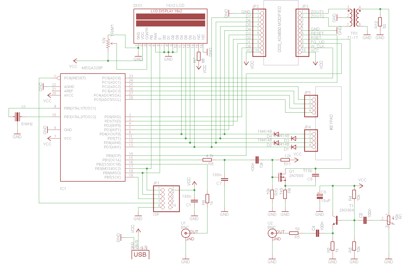
The bulk of hardware consists of Atmega328 that controls 16-key keypad, DDS module, and LCD display. As modulation frequency and sweep timings are derived from Atmega's clock, you need an external clock source, the internal 8MHz clock is too unstable for this
Although the DDS chip can only be used to produce frequencies up to 62.5MHz, the software goes up almost all the way to 125 MHz on assumption that a result of mixing of the set output frequency and the 125MHz clock us used as an output. This is mostly useful for testing FM frequency band and works fine, with the resulting signal being ~12dB lower than the actual DDS output signal that is down in 17..37.5 MHz range, according to the application note AN-423.
In addition to that there is amplitude modulation circuit built around Q1. This is fed with sinewave derived from PWM output of Atmega after filtering through R8,C7. Q1 is biased using R10,R11 and AC modulation signal is applied to its gate through C9. The ~1000Hz modulation signal is generated in software by controlling the PWM output at about 32KHz sample rate. The frequency modulation does not need any additional hardware, this is simply done by changing the carrier frequency that the DDS chip is generating.
The remaining circuit is RF output stage, and a sweep generator trigger signal coming from pin 16 of Atmega. The trigger signal goes high for a duration of frequency sweep, about 250 ms, and then goes low for a little bit, ready to trigger the scope for the next sweep.
The transformer that you need is Minicircuits MCL T1-1T RF Transformer, these are available from eBay.
Obviously this is not a proper lab instrument and instead of even trying to suppress noise it actually relies on noise for FM band range. It is way better than nothing, though, and plenty good for adjusting the dial and working on old-school analog receivers.
Software
The code for the microcontroller is available in my rfgenerator repository at github. For building you need a working make, avr-g++, and avrdude. As usual, I have only built on OSX but the makefile should work without problems on Linux too.
Building
Just type make, and you should get hex and eep files. make flash will try to write the code to microcontroller using avrdude with usbtiny compatible programmer. make clean will clean the clutter from directory, and make erase will try to erase microcontroller's flash memory.
Functions
The user interface is very simple. You can enter two frequencies, A and B by entering frequency in Hz and then pressing A or B button (while entering digits, D key can be used to delete the last digit). In either case, the output will be set to that frequency. Once you have set A frequency, then you can add AM modulation to that carrier by pressing '*', or FM modulation by pressing '#'. In both cases, the carrier will be modulated with ~1000Hz sinewave. Press any key to stop the modulation. Pressing C button will start a frequency sweep function where the output frequency will sweep from A to B over ~250 ms time period, the sweep sync output will be at high logic level while the sweep take place, this can be used to trigger oscilloscope.
The sweep function probably works best with digital scope where we can enable signal averaging, and using a detector probe makes the output look way better. 1N5711 diode followed by 10pF capacitor should work for most things you are likely to use this generator for.