Simple PWM controller using 555 timer
This PWM controller is cheap and easy to build, but has no temperature control and with components shown runs at relatively low frequency.
See my AVR micro based PWM controller for better alternative that has temperature sensing, much higher frequency, and uses less components.
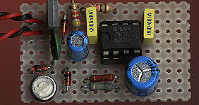
This 555 timer based PWM controller features almost 0..100% pulse width regulation using R1, while keeping the oscillator frequency relatively stable. The frequency is dependent on values of R1 and C1, values shown will give a frequency range from about 170 to 200 Hz. Any 555 chip will do, CMOS is fine as well. Diodes are not critical, I used 1N4148. Total cost of parts is about $2. As the whole thing is quite trivial, it's very easy to build on prototyping board like I did (as you can see, one of capacitors - C1 is replaced with different value, 0.047 uF to be precise):
R2, R3 and C3 form a kickstart circuit which keeps 555 in reset state for about 2 seconds. If you want to use this circuit with V+ other than +12V, then it is a good idea to increase R2 value so that (V+ * R2)/( R2 + R3) is about 2, because the reset signal treshold is about 0.5..1V. If you do not do that, then the kickstart signal will probably stay too close to reset treshold.
Q output of 555 is used to drive the PWM cycle, so the discharge pin is used to drive output transistor instead. This is open collector output, and is used as active low signal, so that the kickstarter will work. D3 protects the output transistor from inductive loads. You may substitute any suitable transistor for Q1, BD140 is 1.5 amp and does not even get warm driving a 80 mm fan without heatsink.
C4 and C5 are power decoupling caps for 555, which generates relatively large peaks with it's push-pull output stage.
The schematics shows connectors that allow to drive 3-wire fan, and still feed the tachometer output to motherboard. However, the tach signal is of no use, because besides a normal tach output it also disappears whenever the PWM cycle removes power from fan. It does keep the motherboard monitor software eternally happy, however.
I tried this controller with 80 mm power supply fan, which worked like a charm. A high-speed, loud-howling CPU fan on my new Celeron 600@855 CPU was not so happy, though. Even after increasing the base frequency by factor of 2 the fan keeps making a sort of lowish frequency groaning noise, which i suspect is resulting from it's low mass that does not keep the fan running smoothly between PWM cycles. It still works, and is currently attached to the CPU fan on a machine as I write this text.
If you want to be really high-tech, then you can use a thermistor between wiper and one end of R1 to make the PWM cycle temperature dependent. It does have a side-effect of changing oscillator frequency along with PWM width, though.
Copyright © Madis Kaal 2000-