Reflow soldering oven project
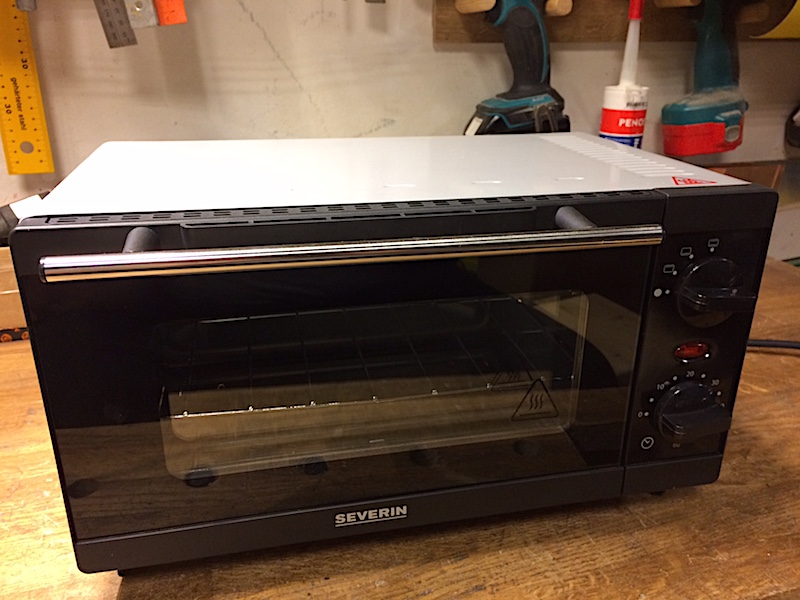
This is the oven I chose as a starting point as for me the main criteria was physical size, and the choices were rather limited. Those who have been through a similar project would have probably noticed few things that make this one a poor choice, namely:
- Plastic parts around the door. Ideally you want an oven that is all metal and glass.
- It has 800W heating elements. Thats marginally ok (more on it later) but you really want about twice as much.
- Small size means that the empty space behing the controls is rather limited, and you will want to mount some pretty chunky stuff there. More space is better.
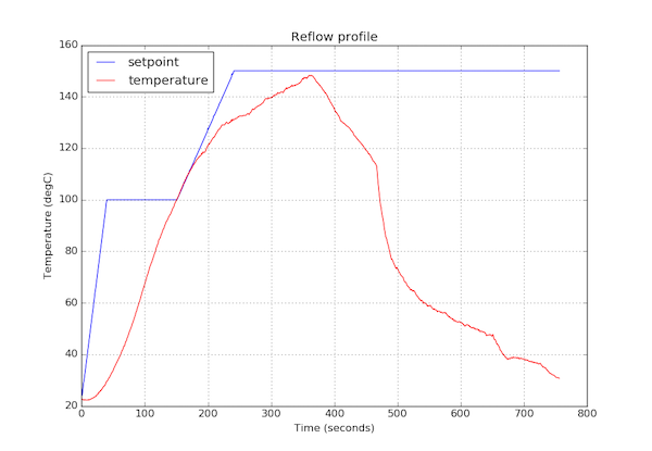
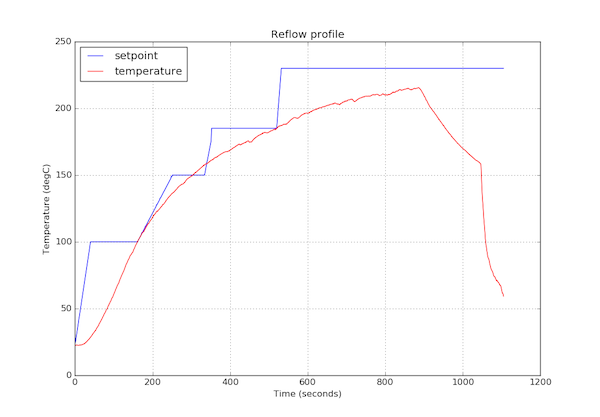
| The first thing I did after writing first bits of code was to just plug an unmodified oven in and see what the temperature rise profile is like. at the peak of the red line the built inthermal switch triggered. This should have made me stop and think a little, as in what oven would not go above 150 degC. The issue here was that my temperature reading code did one bit shift too many and as a result the returned temperatures where only half of the real temperature. |
|
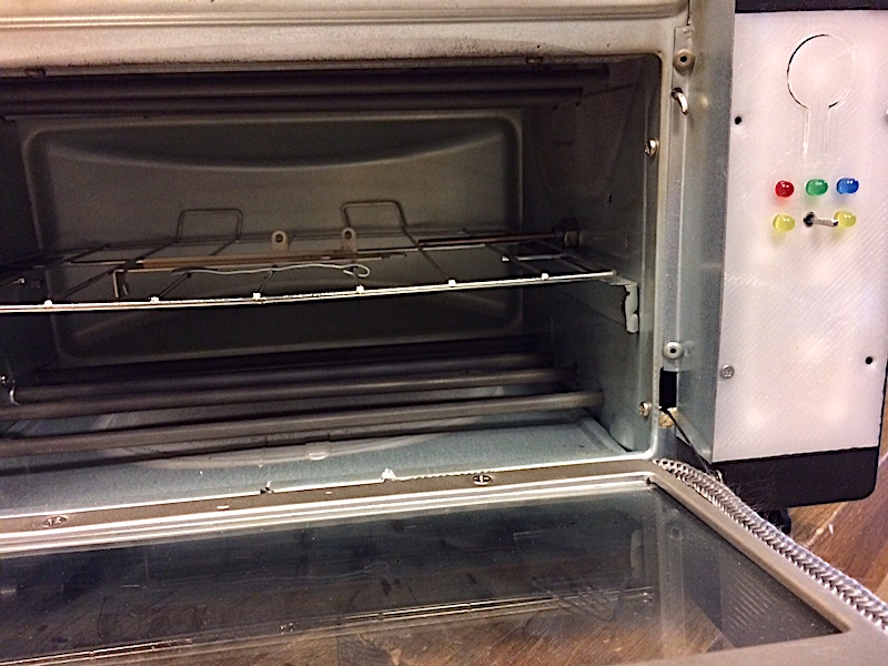
Foolishly, I just proceeded to add insulation to the oven. This is what it looks with the cover off. The oven cavity itself has double ceiling and double back, but the sides and removable bottom are single layer, and sides have big slots where the shelf slides when you open and close the door. The sliding shelf is a problem because of these openings, and because it does not allow for insulating very well.
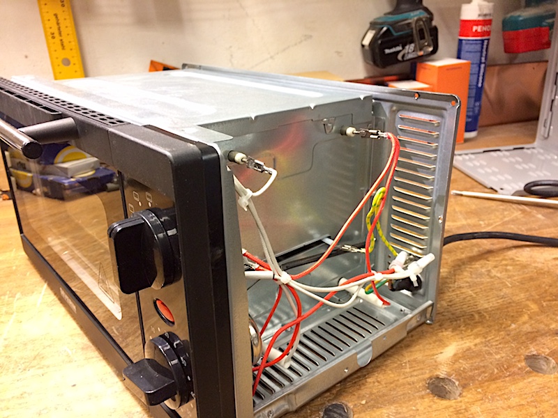
For insulation I used aluminium-backed 25mm rock wool that is meant for insulating fireplaces, and taped the edges and seams over with self-adhesive aluminium tape. For being able to fit the wool on top of oven cavity I removed the double ceiling. I also taped a piece under the oven cavity, and put as much as I could between layers of the curved back (not much space there).When using this type of insulation, make sure that the aluminium foil is well clear of wiring, and ends of heating elements.
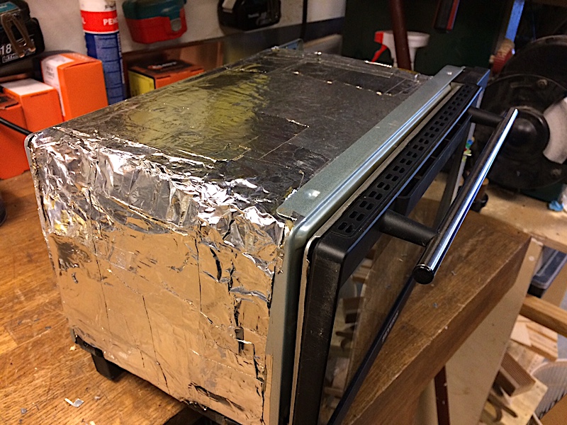
Insulating the oven is not all positive. It does allow your oven to heat up faster and to higher temperature, and keeps the outside of the oven at more reasonable temperature, but it also massively lowers the cooling rate of the oven. Doing it again, I would go for larger and more powerful oven, and less insulation. The importance of cooling rate became clear when I got to the point of actually trying to regulate the temperature precisely to follow the soldering profile curves, as PID controller is quite useless for heavily non-linear system like the insulated oven.
| This is the result of second experiment, with insulation added and thermal switch removed. The temperature reading is still incorrect, so what really happened here was that oven went all the way to 450 degC. This is when plastic pieces around the door started melting. I of course had not realised my mistake, and knowing that 230 degC is the peak temperature for leaded solder reflow profile concluded that I need more power. |
|
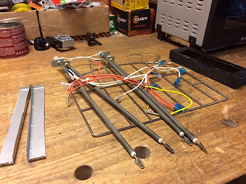
Thats where I bought a second oven for parts donor, and harvested another set of heating elements, wiring, screws, un-melted front panel and some useful pieces of sheet metal from it.
| I mounted the additional heaters between the originals, and did another test run. This time the reading went to about 270 degC without any problems, so I called it good. In reality, the oven was at about 540 degC, and thats really hot. Smoking hot. Boiling and exploding PCB-s kind of hot. My garage still reeks of burned PCB-s. |
|
Electronics
I made up the control circuit as I went along, and it shows especially bad in power supply part. I just took a transformer that physically fit into space behind control panel, and started building power supply around it. 5V supply was not a problem until I added servo for opening the door, and this is where I added the DC/DC converter for that one. Then for 12V fan I had to add a separate 12V regulator because the anemic transformer, although not able to supply the servo at full blast, pushed the rectified output voltage on C4 all the way to 23V. The best option is to get a nice beefy (about 2A) 5V power supply and use a 5V fan. The fan is basically there to keep the side compartement at a reasonable temperature, and you may be able to leave it out, depending on your oven and how much insulation you can have on the side facing the electronics.
The brains of the operation is Atmega328 microcontroller. Atmega168 will also work.
You also dont need all the leds, convection and heating are the actually useful ones. Convection led is on when the oven is running, and heating lights up when the AC voltage is actually applied ot heating elements.
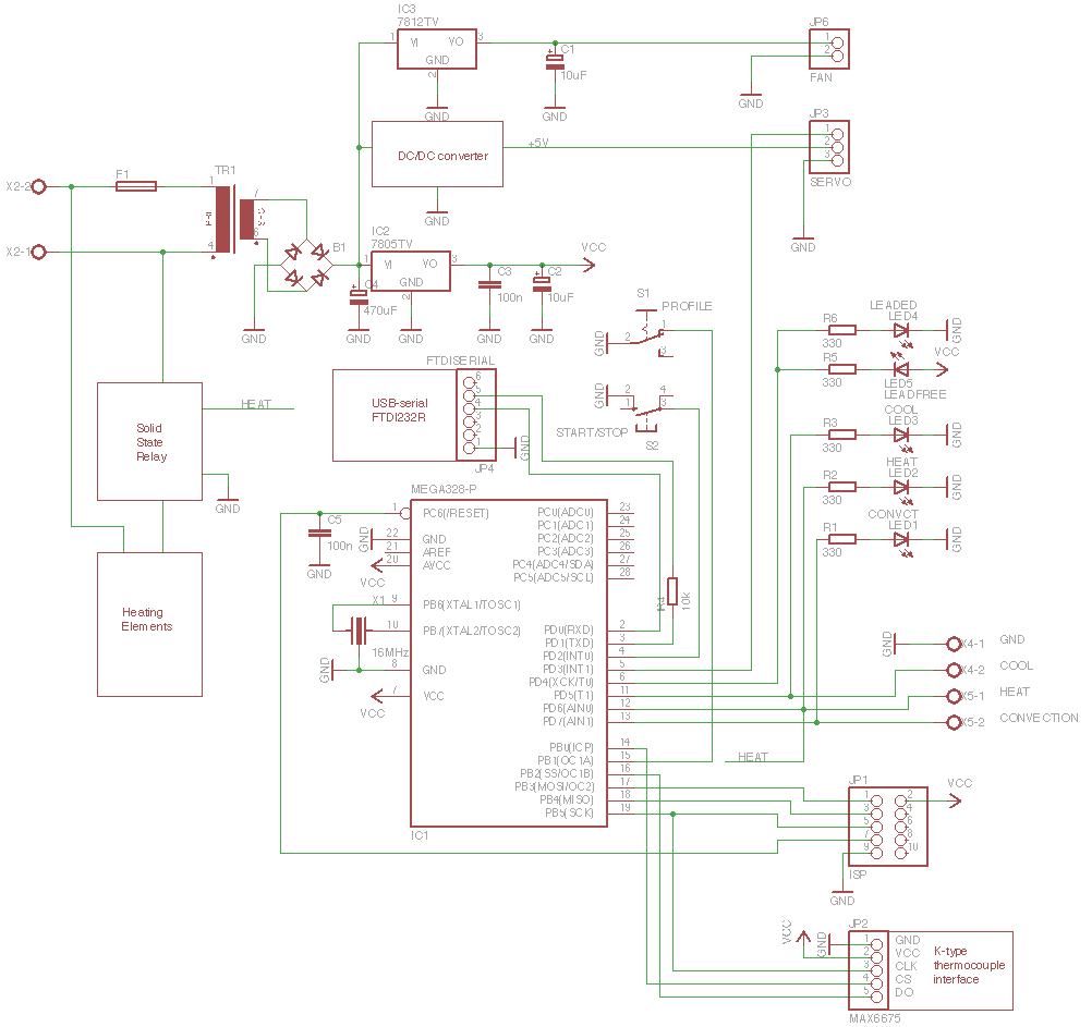
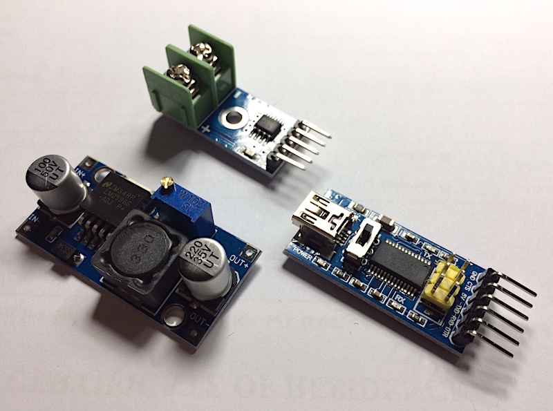
Here are the 3 modules shown on schematic diagram, they are all cheap and easy to get from eBay. If you get a better power supply then you probably will not need the DC/DC converter, and the FTDI USB-serial module is also optional, although highly useful for tuning and debugging. For the solid state relay I bought a cheap Fotek-branded 25A SSR, also from eBay.
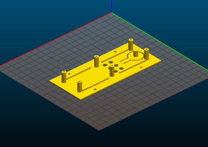
Construction-wise I made a large cut-out in original front panel, and covered it with 3D printed part. The new front panel has turrets on the back for mounting a board with components, and also a cut-out that works as start/stop button. Doing it again I would definately go for 2 stacked boards, the contraption that I ended up looks like a hedgehog with parts sticking out from both sides.
Also visible in this picture are few mods:
- Metal heat shield between oven and front panel
- Sticking out from the front is a bent piece of wire from coat hanger, the other end is attached to servo. This is what pushes the door slightly open at the end of the soldering cycle.
- Oven door insulation rope glued to the door to make it more airtight, as part of overall thermal insulation.
- The added heating elements, and new support rails for shelf that also cover up the orignal cutouts where the shelf was sliding.
- Thercmocouple sticking out into oven through the right side.
| The back side of the new front panel looks like this. The turret on the back of the cut-out is just the right height to hit a pushbutton mounted on circuit board. |
|
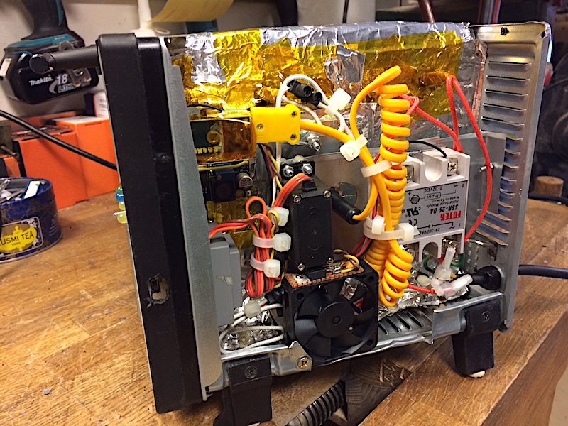
The completed side compartement. Note the liberal application of capton tape for electrical insulation. A piece of sheet metal attacked to the frame is used to mount the SSR and servo motor, and also acts as forms a channel behind it for air flow.Below the servo is a small fan that came out of my Rigol scope, with 12V regulator attached to it. The mounting plate has a hole in it through which the thermocouple goes into oven (the thick yellow spiral cable). On the left you can see the gray power transformer, DC/DC converter module, and thermocouple amplifier module sticking out from circuit board. On a side of a front panel there is a hole for connecting USB cable to the FTDI module that is mounted on the other side of circuit board. There is a piece of 1.5mm thick aluminium behind the SSR to improve the thermal conductivity to mounting plate, the sheet metal piece from the double ceiling is too thin on itself to make a good surface contact. The entire oven by the way is made from paper-thin and soft sheet metal, and the only thing giving it some ridgidity is that when it is all assembled then there are multiple layers of metal in each direction. The fan sucks in air from an opening that I cut into outer case, blows it behing the mounting plate, and out from pre-existing cuts in frame and outer case.
Using the oven
The completed oven is simplicity itself. You flick the profile selection switch to leaded or lead-free position, and press the start button. The process runs, and at the end the servo will push the door open. To speed up the cooling, open the door all the way manually. The servo will move to closed position when the oven has cooled to 60 degrees. Obviously the door is also closed at the start of process, and when you plug the oven in. In case of temperature sensor failure the the oven will reset, and selected profile leds will bling on and off alternatively. You can stop the running process at any time by pressing the start button again. In this case the door will not pushed open by servo.
Software
All the code is available in reflow_oven repository at GitHub, MIT licensed.
The main loop is in reflow_controller.cpp, and it just turns the process and serial console at about 500us interval of the timer0 interrupts. The timer interrupt handler calls other periodic tasks - 20ms interval servo pulse, reading the temperature every 220ms, running PWM for the heaters, incrementing the seconds counter, and updating buttons. The rest of the code in this file is for serial console where you can read the current temperature, run the oven to specific temperature, dislay and change oven settings. More on the serial console below.
oven.hpp defines the interface to physical oven, and acts as a proxy to temperature sensing and servo control too. The important part of it is PWM logic that runs of the timer interrupt, and has a about half second full period, with 128 steps.
process.cpp has the code for actual reflow soldering process, using PID controller and oven interface. There are two defined profiles, selected based on profile selection switch position. Each profile has a list of steps, where some are {temperature,time} pairs, and some are special steps like {ProfileStep::PROCESS_DONE,0}. The temperature pairs define the target temperature at the end of step, and time to get there. The process then divides the temperature change to a number of smaller steps so that temperature setpoint would be adjusted gradually over entire step time. The single-presision floats are used, and this leads to accumulating error, so the steps are not necessarily ending up at exactly the right temperature, and last one may cause a bigger or smaller step change. There are special steps for opening and closing the door, and marking the end of profile.
Despite spending ages on trying to find PID coefficents that would work ok for my oven, I ended up just tinkering with the profile steps so that the temperature overshoots are taken into account. With PID control alone you either have to slow down the temperature rise, and creep up very slowly for not overshooting massively, or tolerate the temperature overshooting the setpoint by 10-20 degC. I wanted fast and good, so I just built up the profile steps to give me good enough results. Also, as part of avoiding overshooting, the PID controller is reset at the beginning of each step, to clear out accumulated integral value.
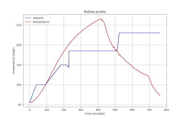
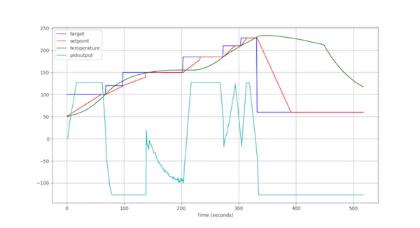
| This is the result of currently defined leaded solder profile. Blue line shows the target setpoint for each step, and red line shows the PID setpoint every second. The green line is the actual oven temperature, and pale blue shows the output of the PID controller. Notice how the PID setpoint stays below the oven temperature for second half of initial temperature increase. All this time the temperature is rising because it is overshooting the initial 100 degC setpoint. After the flat preheating part the overshoot is less of a problem because each next step just goes higher, and at the end the door will be pushed open. The temperature will still overshoot by few degrees, but the temperature will start dropping after few seconds. The cooling is very slow, and this is with the door slightly open. |
|
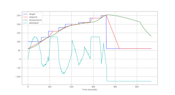
| This is how the lead-free solder profile currently looks like. I'm not planning to use this one much, so I did not spend much time on tweaking it. It'll get the job done as it is, I think. Again the biggest issue is probably the slow cooling rate. On both of the charts there is a sharp knee on a green line at the end, this is where I manually fully opened the door. This results in much more acceptable cooling rate, but would require something different than simply a servo to get the door open. Setting up a fan to blow cool air into oven is probably easier way to go than opening the door all the way, and active cooling would also allow much better temperature control and profile following during the process. |
|
servo.hpp implements servo motor control, and also limits the rate of change in servo position to keep the current consumption under control. If you have a good power supply then the rate limiting would not be needed, but in my case the crappy power transformer's output voltage dipped so low that 5V supply to microcontroller dropped below brownout threshold, causing microcontroller to reset.
temperaturesensor.hpp has raw value reading method that is called from timer interrupt, as the calls must be rate limited because of MAX6657 long conversion time. The raw value is filtered with 4 step moving average filter, and then the Read() and IsConnected() methods can be called to get the latest updated value as often as needed. the IsConnected() method relies on MAX6657 sensor fault flag, and returns true if thermocouple is not connected or has failed open. If this happens then the code will reset the oven and blink the selected solder profile leds until the sensor fault is cleared.
serial.hpp implements a very simplistic polled serial I/O for serial console, with helper methods for printing numbers and strings.
Serial console
The serial console feature proved invaluable for configuring and testing the oven. You can just connect to the USB-serial module with terminal emulator, or with something like screen /dev/tty.usbserial-A50285BI 38400,n,8,1 on OSX or Linux, but all the charts above are generated by a debuglogger.py python script.
The script does two things. Firstly it is a (very poor) terminal emulator, displaying and logging everything it receives from serial port, and sending characters that are typed on keyboard to serial port. Secondly, it is looking for "Starting" and "Stopping" and interprets any data lines in between as time series of comma-separated values for charting. Any empty lines or lines starting with '#' are ignored, and the first data line must define the field names and data types. The output from oven would look something like this when the process is started:
Starting time#i4, target#f4, setpoint#f4, temperature#f4, pidoutput#i4 1,100.000,60.174,59.500,0 2,100.000,60.849,59.500,12 3,100.000,61.524,59.750,18 4,100.000,62.199,59.750,29 Stopping
The current script can handle up to 6 columns, limited by number of line color definitions.
Copyright © Madis Kaal 2000-