This is an update to my previous balanced microphone amplifier project, with the main difference being in power supply section. Instead of requiring mains power and including a power transformer, this version runs from 12V DC supply.
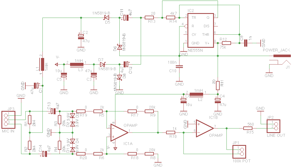
12V (500 mA power supply would be plenty) comes into power input jack J1, and supplies the 555 timer that is configured to produce approximately 100kHZ square wave. Its output Q drives 2 charge pumps through current limiting resistor R13. D5,D6,C2,C11 form a voltage doubler circuit for phantom power supply. D7,D8,C3,C12 form a voltage inverting circuit to produce negative power supply rail for opamp.
The 555 and charge pumps produce a lot of switching noise on all power rails. I had some low-current 1mH inductors kicking around, so I added these to filter the power supply. You can probably get the same result with much less inductance. Also try to keep the layout sensible so that the power supply section is separated and grounds for the power supply and amplifier sections are connected at one point near the power input jack.
The amplifier itself is basically the same as the first version, except that phantom power supply resistors to microphone have been reduced to enable the maximum allows 10mA current to be supplied to microphone. The precise value of R1,R2 and R3,R4 is not that important, but they should be paired to have a same value. The critical resistors are R5,R6 pair and R8,R9 pair. The schematics diagram shows second resistors with 0 value in series with these. You would actually use these for matching the resistance by adding a series resistor if needed. Pick the opamp that you like, just watch out for the power supply limits. NE5532 is a good option to start from.
I kept the output DC coupled, but added a series 560 ohm resistor for current limiting in case the output is shorted.