I recently noticed that the links to EPROM programmes in my Basic52 bootstrapping page were all broken. After correcting them to point to appropriate pages in internet archive as a quick fix, I had a thought that I do not actually have a convenient way to read and write EPROMS myself.
I mostly use Atmel AVR series microcontrollers, with homebrew USBTinyISP programmer (for schematics see Adafruit site). After the EEPROM programming with USBTinyISP, EPROM programmer looked like a good idea. After a false start with Atmega168 that turned out to have 1 pin too few, and switching to Atmega1284P, here is EPROM programming solution with USB interface that you can use on your Mac, and Linux, and maybe even on Windows if you get the python USB library to work on it (click on schematics to open full size version in new window):
Hardware
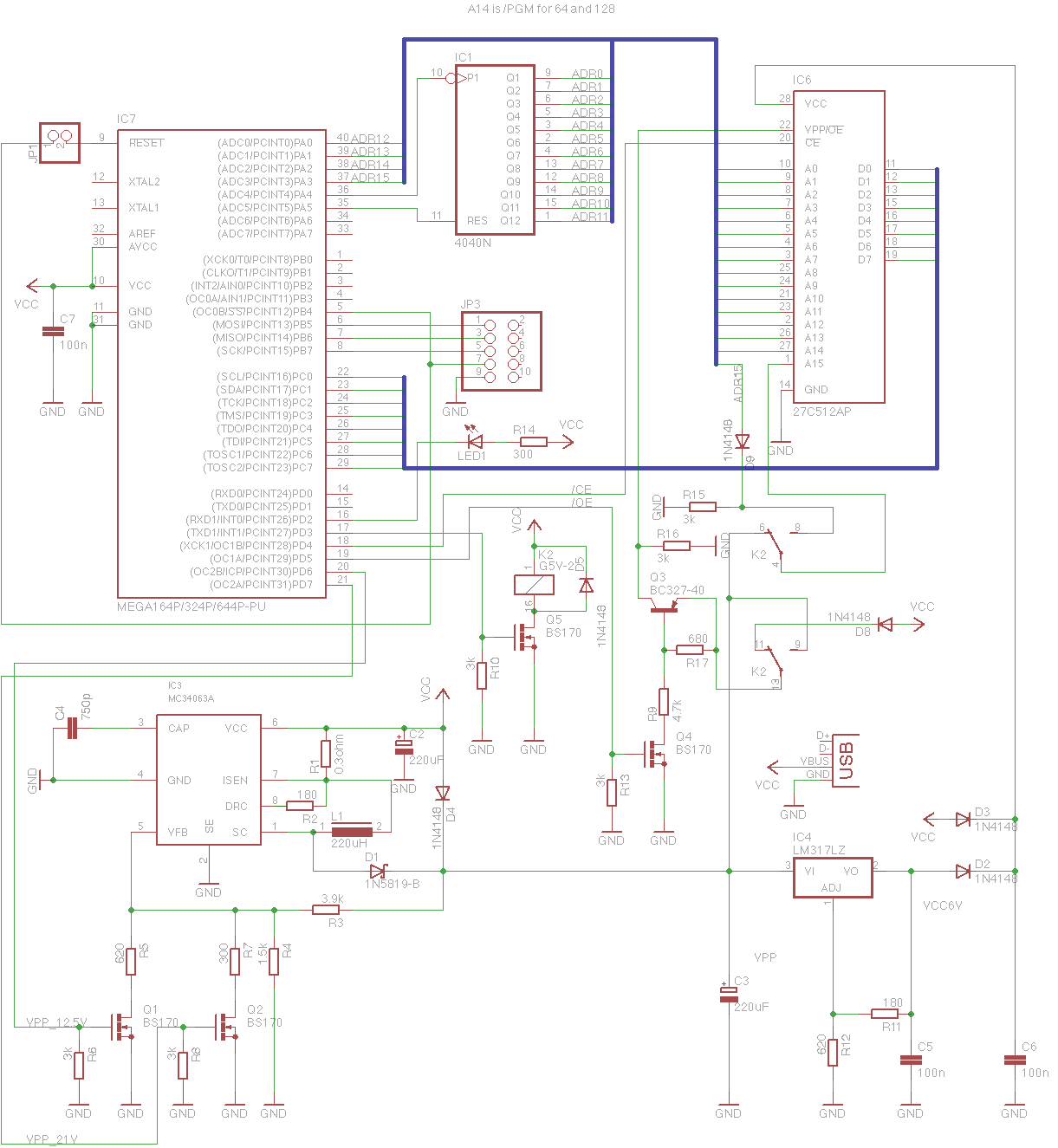
As I said, I used Atmega1284P for the brains of the operation, but most of the code space and RAM is unused. I just saw no point of buying less capable variant with insignificant price difference. It is configured to run from internal 8MHz oscillator.
The ISP programming connector (I have nonstandard layout) is also used to communicate with the firmware during normal use, so there is a jumper on the reset pin that needs to be shorted for flashing the firmware in circuit, and needs to be open for normal use. The reset signal from the connector is also wired to Slave Select signal to make the SPI slave logic work correctly.
CD4040 counter is used for lower 12 address bits to save microcontroller I/O pins, while 4 highest addresses are wired directly to microcontroller. ADR14 signal works as programming pulse input for 2764 and 27128 EPROMS. ADR15 is only used for 27512, and for the smaller size EPROMs the pin 1 is programming voltage input.
EPROM data bus is wired directly to PORTC, and it is up to firmware to ensure that PORTC is set to all inputs when /OE and /CE signals are both driven low. The /OE input is also used as programming voltage input for 27512, this is why there is a switching circuit with Q3 and Q4. The programming voltage is switched to correct pins with a 5V relay, driven with Q5.
Handful of diodes protect circuit from VPP going into wrong places, and also provide default voltages that high VPP can override. D4 ensures that there is always 5V (minus diode drop) on VPP rail, and D3 similarily provides VCC for EPROM. When VPP goes high enough for IC4 to produce output voltage higher than 5V minus a diode drop then EPROM VCC voltage will rise to above 5V level for programming.
Programming voltage is generated by boosting 5V using the IC3. In normal state it is set to regulate its output below 5V, and is not switching. 5V will flow to its output through L1, D1. There is also bypass diode D4, this seems to help to keep the circuit stable in this semi-sleeping state. Q1 and Q2 allow to reconfigure the feedback voltage divider by putting R5 or R7 in parallel with R4, enabling the switcher to boost VPP to about 12.5V or 21.5V. The VPP will take some time to raise and fall, and firmware must take it into account. Firmware also turns on the led whenever it turns on the VPP switcher.
The small fets can be substituted with 2N7000 (this is what I used)
The current draw on the 5V supply is quite high when using 21V programming voltage. Even with 12V programming voltage the total current draw is over 160mA when programming 27C64. With 21V the power supply must probably be able to provide at least 400mA, so you cannot just plug the thing to any regular USB port. The 500mA-1A USB power supplies are cheap and plentiful these days, and any of these should work.
Software
All C++ code is available at GitHub, in my epromdude repository. I also made hex files available if you do not want to build the code yourself. For building you need a working make, avr-g++, and avrdude. As usual, I have only build on OSX, feel free to contribute with build instructions for other platforms
Building
Just type make, and you should get hex and eep files. make flash will try to write the code to microcontroller using avrdude with usbtiny compatible programmer. make clean will clean the clutter from directory, and make erase will try to erase microcontroller's flash memory.
Code contents
I've commeted the code heavily, you should have no trouble understanding what is going on. The main loop basically sits and waits for interrupts to happen, and after the interrupt is serviced checks if that resulted in a command that needs to be executed.
SPI communication is handled in SPISLAVE class where receive() method handles the actual communication with SPI master, and process_command() executes the received commands.
EPROM reading and writing functionality is contained in EPROM class. The programming over USB attached SPI bus is not going to be lighting fast anyway, so I did not see a point of implementing any fancy programming algorithms, just a good old Intelligent method of 1ms pulses followed by one longer pulse to make the programmed value 'stick'.
epromdude.py is the actual programming piece that talks over the USB to the firmware. You can read and write full or partial EPROM content to/from binary files. Writing HEX files is also supported. Running it without options will display short help page:
use: python epromdude.py --write --device devicename --vpp voltage [--adr epromadr --count bytecount] [--hex|--bin] filename python epromdude.py --read --device devicename [--adr epromadr --count bytecount] filename For write adr and count arguments only apply to binary files count and adr can be decimal, or hex with 0x prefix supported devices: 27128 27256 27512 2764 supported voltages: 21v 5v 12v
Enjoy.