Click on diagram to get full-size image in new window:
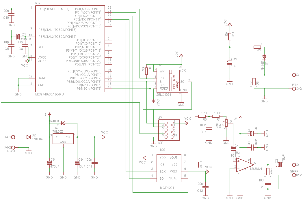
The main piece of a hardware is Atmega168 in my case but any Atmega that can go up to 20MHz will do. Going with lower clock frequency is possible but requires change in code to keep the sampling rate right.
Push button is connected to INT0 external interrupt input through a noise-canceling circuit.
8-bit audio samples are stored in 25LC1024 EEPROM, and played back through MCP4901 8-bit serial DAC. Analog output of a DAC is passed through crude low-pass filter R8,C14 and then goes to voltage divider formed by R1,R10. The audio signal then goes to audio amplifier for which I used LM386. You may want to go for something beefier if you need louder doorbell. As usual for me, there is a non-standard layout ISP connector JP1 that allows to power the thing over USB without external power supply.
The external power supply should to be DC in 7-12V range. For lower voltage you will need to modify the fuse settings for lower brownout detection level for AVR, or remove the power 7805 and/or diodes and supply 5V directly. D2 is for reverse voltage protection, and D3 allows USB power to also power the audio amp if external power is not supplied.
You can build it in whatever way works for you, but good grounding and bypassing of audio amplifier and DAC is critical for usable audio quality and low noise. C1 and C2 should be very close to audio amp, and all ground connections in audio path, including DAC VSS should be made to one point that is then connected directly to power input connector's ground.
All C++ code is available at GitHub, in my doorbell2 repository. I also made hex files available if you do not want to build the code yourself. For building you need a working make, avr-g++, and avrdude. I've only built on OSX.
Just type make, and you should get hex file. make flash will try to write the code to microcontroller using avrdude with usbtiny compatible programmer. make clean will clean the clutter from directory, and make erase will try to erase microcontroller's flash memory.
There is not much of it. The main loop just sleeps and resets watchdog, all the work is done in interrupt handlers. After setting up I/O the main function scans through EEPROM contents to find the end of audio. For this to work the EEPROM should be erased to 0xff-s before writing audio file to it.
Falling edge on INT0 starts audio playback by enabling timer interrupts and setting EEPROM up for sequential data reads. If everything is fine, then the button is disabled to avoid re-triggering during playback.
Timer1 overflow interrupt is used to time the audio playback. While the playback is still going on, the interrupt handler first pulses DAC's LDAC input to transfer previously loaded value to output, and then loads new value to DAC while also reading next byte out of EEPROM.
The timer interrupts are happinging at 22050 Hz, which is a compromise between audio quality and playback length. This gives about 6 seconds of audio using a single 25LC1024 EEPROM chip.
The audio data needs to be raw unsigned 8-bit PCM, with 22050 Hz sample rate. For example, in Audacity you'd start with whatever audio file you have, create a clip of 6 seconds or less. Set your project rate to 22050 Hz, convert Stereo track to mono if needed, and then resample to 22050 Hz sample rate. Then from Export option in the File menu take defaults for header, in the next dialog click on options button and choose "Raw (header-less)" and "Unsigned 8 bit PCM".
Now that you have your audio data, you need to get it into 25LC1024. I used my USBTinyISP programmer with memdude. For example, to erase the EEPROM and fill it up with 1000Hz sinewave, I'd do:
$ python memdude.py --device 25lc1024 --erase erasing device $ python memdude.py --write --device 25lc1024 --bin 1000hz.raw programming device 00020000
Enjoy.
Copyright © Madis Kaal 2000-